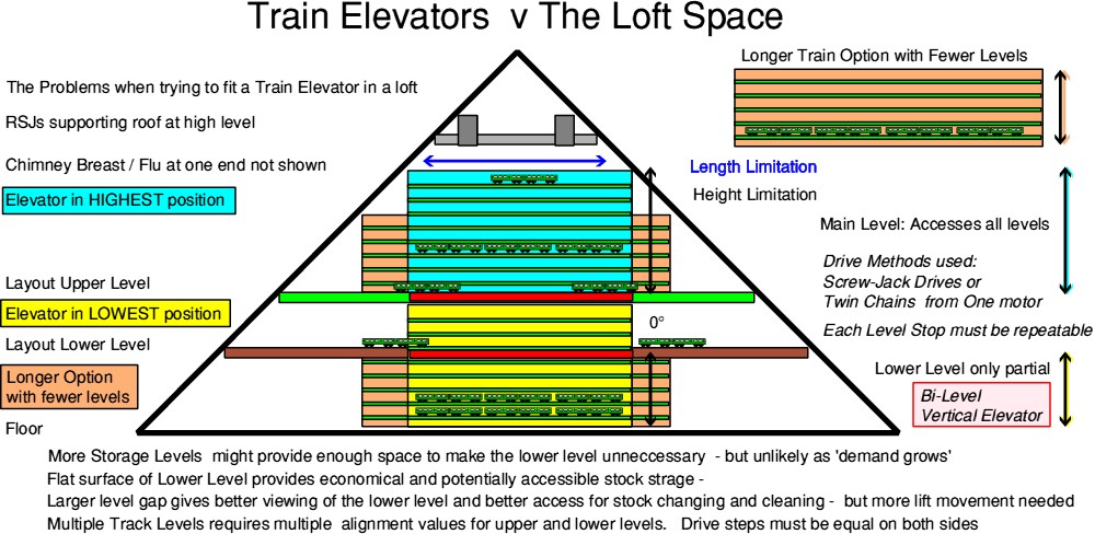
The origins of the Bi-Level design come from my loft layout having a 'lower storage level' and needing a 10 metre 2%
incline to give barely enough space [20cm] for the lower level to be visible and accessible !
Being located in a loft with 42degree roof sloping either side meant that a 'Conventional' Train Elevator
would not be very effective as it would be resitricted by the diminishing width available as it rose.
For our later 'Skandi2' / Somehwere in Scandinavia Multi-level layout we have a Helix connecting the 3 levels
within a frame of 1.2m x 1.1m x 0.3m with separate, level, passing tracks across the front and back {radius approx 50-55cm}
Our lower level storage in the loft layout DOES include flat reverse-loops at each end - of about 500-600mm radius -
but these are at the sides of the loft and any attempt to climb in a helix would require them to be moved inwards
We discussed a Pattenoster Style design before I started to build a bi-level elevator using 2 Satellite Dish Screw jacks
to provide the controlled movement of a single elevator. (They are still in the garage after abandoning that method)
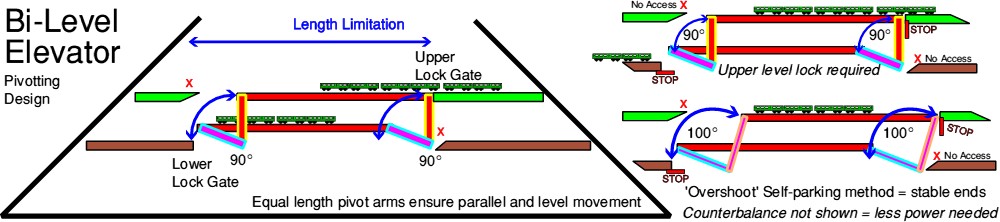
This 'Canal Lock Style' design allows for a very simple set of mechanisms: both for the height change and the
entry-exit release.
Basically 2 counterbalanced arms pivot 90 degrees for the required lift: Once the height change is known, the arm length
becomes set ..... as it swings 90 degrees it also moves the same distance horizontally ... butting up to the entry/exit
at each level which also acts as the end stop.
Therefore a 30cm height change also moves 30cm across.
The length will depend on the longest expected train - maybe 2m.
Even though no sideways movement is intended, as with any horizontal traverser, the ends should be made to be self-aligning
without the problems seen on many horizontal traversers at shows - great reducing train running activity !
Therefore a V-shaped catchment aligner and end stop is used and set for the correct track alignment at each end:
Each end ONLY needs to align with its single specific entry/exit ... it does not have to be a compromise over 'many'.
Precision engineering and rigidity is achieved by using Aluminium Square Tube for the support and pivots.
Roller bearings and either stainless or aluminum rod are readily available to aid the pivots.
Unlike the original idea of using a pair of Satellite dish screws jacks - which required close synchronisation and pulse counting
the rotational drive for the bi-level 'canal lock' design has no such restriction - 2 identically sized arms will always pivot the elevator in
a perfect horizontal plane. The motor load is minimised by counterbalancing - although obviously the train load will vary.
The 1st thought of counterbalance arms would be a straight extension of the pivot arms below the lower level - this may restrict
access or movment .... so a 90 degree offset would allow all of the mechanism to be 'above' (the Lower) board.
'Locking' in position is unlikely to be required at the lower level, but at the upper level 2 options exist:
Either use a solenoid to engage a locking pin ( and at the same time control power on the track )
or allow movement beyond the 90 degrees so that the upper stop is on a slight descent: self-parking.
For those wanting to operate their bi-level elevator like the Lynton & Lynmouth Cliff Railway; it could be operated by a moving
'over centre' counterweight - which biasses the deck either up or down.
|