|
Phil and Lin Spiegelhalter
|
|
 |
|
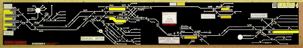
I devised this system in the late 70's in order to provide the most effective control of my Beechingless Barnstaple layout as simply as possible! (The later Zero-1 Mimic version of the same trackplan is shown above) The requirement was to provide 4 identical cab controllers, which could control any train, anywhere, whilst avoiding that most off-putting of analogue/dc scenarios; of running a loco into a dead section that so clearly demonstrates the disadvantage of 'traditional' cab control or dedicated regional controllers.
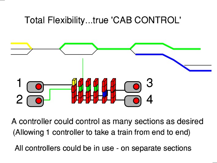 As a model of North Devon, featuring the daily Atlantic Coast Express, multi-portion train, which required splitting or recombining at Barnstaple Junction, a means of allowing 2 trains in each platform was essential. My elder brother had previously rebuilt the family-layout with Trix-Twin, which would allow this; but I restarted in 2-rail, Reading this in 2009/2024+, you may be wondering why I didn't simply go digital?: well, of course, I did; with Zero-1... but there was a 2-year wait from its announcement to release, and recent discussions with others (2008!) have shown that, although the boundaries have moved, there are many, particularly in N-gauge, for whom a good analogue operating system was still preferred. 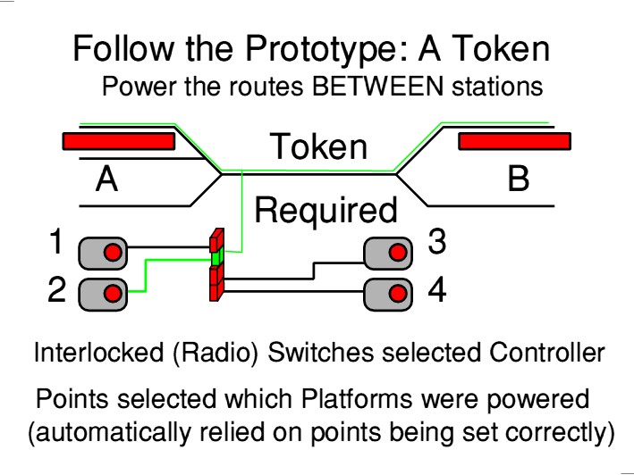 Any Controller Any Track: Open Access The first and most fundamental requirement was for each controller to have equal access to all locations. The layout was built in a loft, with a central operating well, and so a single Mimic Panel sufficed. However, for a larger, club layout with multiple operators, duplicate panels would not present a problem today, with simple logic interlinking, using a single Push-button to Select a section, described later. Offering 2-controllers for any area is very easy to implement by using centre-off DPDT Toggle Switches, which would provide immediate visual indication of which controller is selected to a section of track, and implicitly prevents both being selected at the same time; thus ensuring electrical isolation is maintained. If common-return wiring was usable, only one connector would need to switch track power; leaving the second pair to operate a visual indication on the panel by lighting the track in that controller's colour. Therefore, a 2-Controller version of this system, for a one person smaller layout would be very easy to implement. In the case of my layout, it fell naturally into 4 sections where train movement could be taking place simultaneously: 2 routes from Exeter/Taunton to Barnstaple Junction, and 2 branches from the Junction to Torrington or Ilfracombe. As alternatives, shunting could be taking place in the yard or Destinations. As a home layout, the short running lengths involved on a 3m x 5m layout (00) precluded the need for these to be additional controllers at additional expense. Any controller could take a train from its starting point to its destination, and then shunt it into a return formation.
4-Position Rotary switches, with 3 poles could be used to expand the system to 4 controllers, but with the severe disadvantage of having to pass through
controllers '2' and '3' when changing from '1' to '4' and no
Radios used to offer Multiple Waveband Push-button Selection with Interlocked switches, which internally also had many contacts;
Multiple contacts provided for DPDT switching of the track, together with a separate track-light for the track diagram, - for which 4 colours would be the preference.
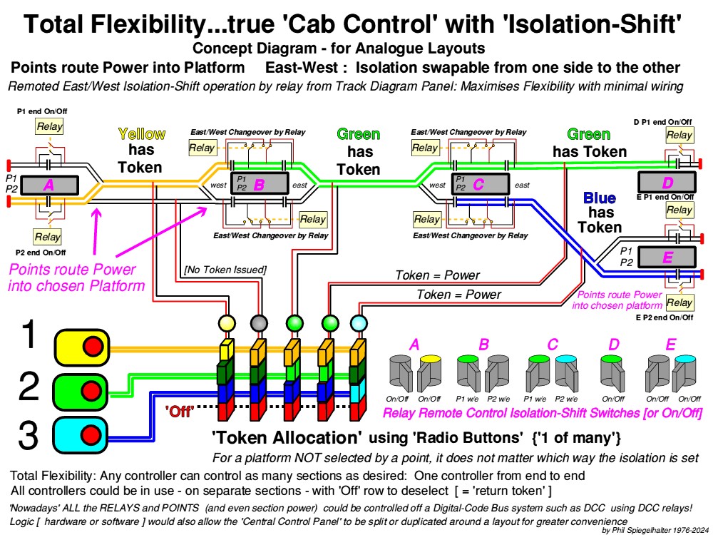
Here lies the first of the 2 main variations from 'cab control: Instead of wiring a switch from the 'cab selector' to each
section of track, only the 'Tracks between places' or Headshunts are 'Powered' or directly selectable.
Isolation is then provided within the length of the platform, so that routes B and C remain electrically separate. 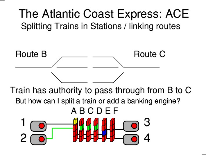 By having 2 pairs of isolating gaps in the platform - with room for about 1½ locomotives at each end, and powered off their respective 'Powered Sections'- a 2nd loco can be driven into the platform behind the first. Unlike 'cab control', the CENTRE SECTION is not Powered 'On/Off', but the ISOLATION is transferred from one end to the other: A local relay c/o switch, operated from the control panel allocates it to 'B' or 'C'.
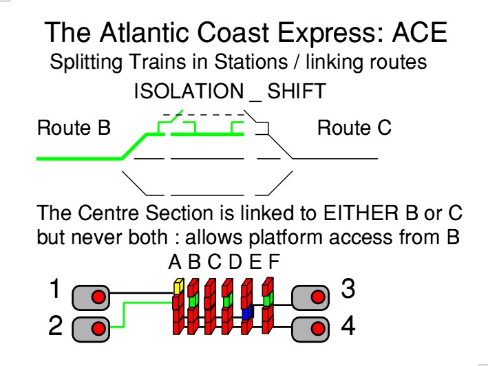 Operationally we do not see a loco suddenly stop, mid move: if it has a Controller and route, it has power. Obviously there is still some scope for error - such as forgetting to shift the isolation - but by minimising the number of 'power' switches, with the others being 'slaves', the problem is minimised, and never occurs when a through route has been set.
The 'Token' sections for this large layout are therefore: The Connecting Routes and Headshunts
If latching push button were used, in the simplest implementation, a long walk may be required to release a
Token Section from another Controller. This would be avoided by non-latching buttons, which 'Set' a latch
and in the ultimate version, would illuminate that Token Section on each panel in its colour.
On each panel, an adjacent 'Release' button would de-select first, the local controller, and with a sustained,
or additional button, a remote controller. The 'logic' is simpler and perhaps 'safer' with the additional button.
|