Fillin Logo gif

Phil and Lin Spiegelhalter - Fillin

Welcome to one of our Railway Pages.
This page describes how an overlay map of the London Underground System can be created and mounted over the matching Traintrackr® Animated Display.

A NEW VERSION [v10] including THE ELIZABETH LINE has been created by Paul Griffiths, and his latest PDF without LT Logo is available below [Version 11] :


PDF file of Overlay 11 for Traintrackr® Display including Elizabeth Line

The overlay shown below is the version I originally created for the earlier 'Large London' Traintrackr® and the overlay for that can still be downloaded here.

A3 Overlay Printout for the Large London PCB from Traintrackr®
and
Picture Frame Mounting using an A3 Commercial Frame with 3mm thick Acrylic glazing
Inspired by the Large London Animated Display created by Richard Hawthorn of Traintrackr® 
 Fillin Logo gif

pcb_oblique.jpg - 111Kb

Large London is a LIVE Realtime Display, produced by Traintrackr®, of Trains-in-Stations on the Underground including the Docklands Light Railway and Waterloo & City Line.

The Overlay when Backlit by Traintrackr® and Framed

framed_map.jpg - 244Kb

The Traintrackr® display updates every second, and shows Station Occupation using Line-Colours, but not Track Occupation. Northern Line Trains are shown in White rather than Black.
Trains will disappear when between stations; especially when on the outer sections where it can take several minutes to reach the next station.
This is a Realtime, Topological, Live Display using data provided by TFL via WiFi, and not an accelerated Arcade Game.


Set it up and Test it First
As purchased in December 2021, this is a 400mm x 301mm PCB with about 330 RGB LEDs in the pattern of the well known Topological Underground Map
My version has a 5V USB power socket mounted on the front; in the lower left corner, however other versions may have differing power connections !
LED brightness can be adjusted, and a brighter setting may be preferable when using the overlay than without, and will depend on paper weight.

UPDATE: I have since ordered a 90° USB B Type adapter with which avoids cutting through the frame for the USB Power Access - see later...

No Modification to the Large London PCB display is required.
A matching USB lead can be bought for extra length or slimming down the USB plug cover at no risk to the original.
No liability accepted for following, adopting or altering information given here.
We have no connection with Traintrackr other than as a customer, and my thanks due to Richard of Traintackr® for providing the LED positions electronically.

The Overlay - as printed [ but shown here as a low resolution gif ]
LondonTrackb.gif - 106Kb

As the London Underground Maps, fonts, and Logos are copyright TFL, the text used in my file is 5.2pt Homerton / Helvetica, and there is no representation of the Underground Logo.
The drawing was created in !Artworks vector drawing software originally written for use on Acorn RISC OS Systems, and still my daily preference.
RISC OS is freely downloadable from RiscOS Open Org, and can be run on many devices including a Raspberry Pi, PinebookPro, or under emulation on PC or Mac with Virtual Acorn.

Download a PDF file to print the Overlay onto A3 at 100%
Two versions are currently available for free-download from this website. Setting the Printer to its densest settings will benefit the fine print.
London Overlay with some Line Colour Station Names uses different colours for some stations to help differentiate them
and
London Overlay with Monochrome Station Names uses Black for ALL station names for maximum visibility

The printout needs to be in contact with the LEDs - so that a crisp image is seen throough the paper. The slightest gap will result in a soft fuzzy image.

Modifying a Commercial Frame to Fit the PCB - NO modification of the PCB required
framing0.gif - 84Kb

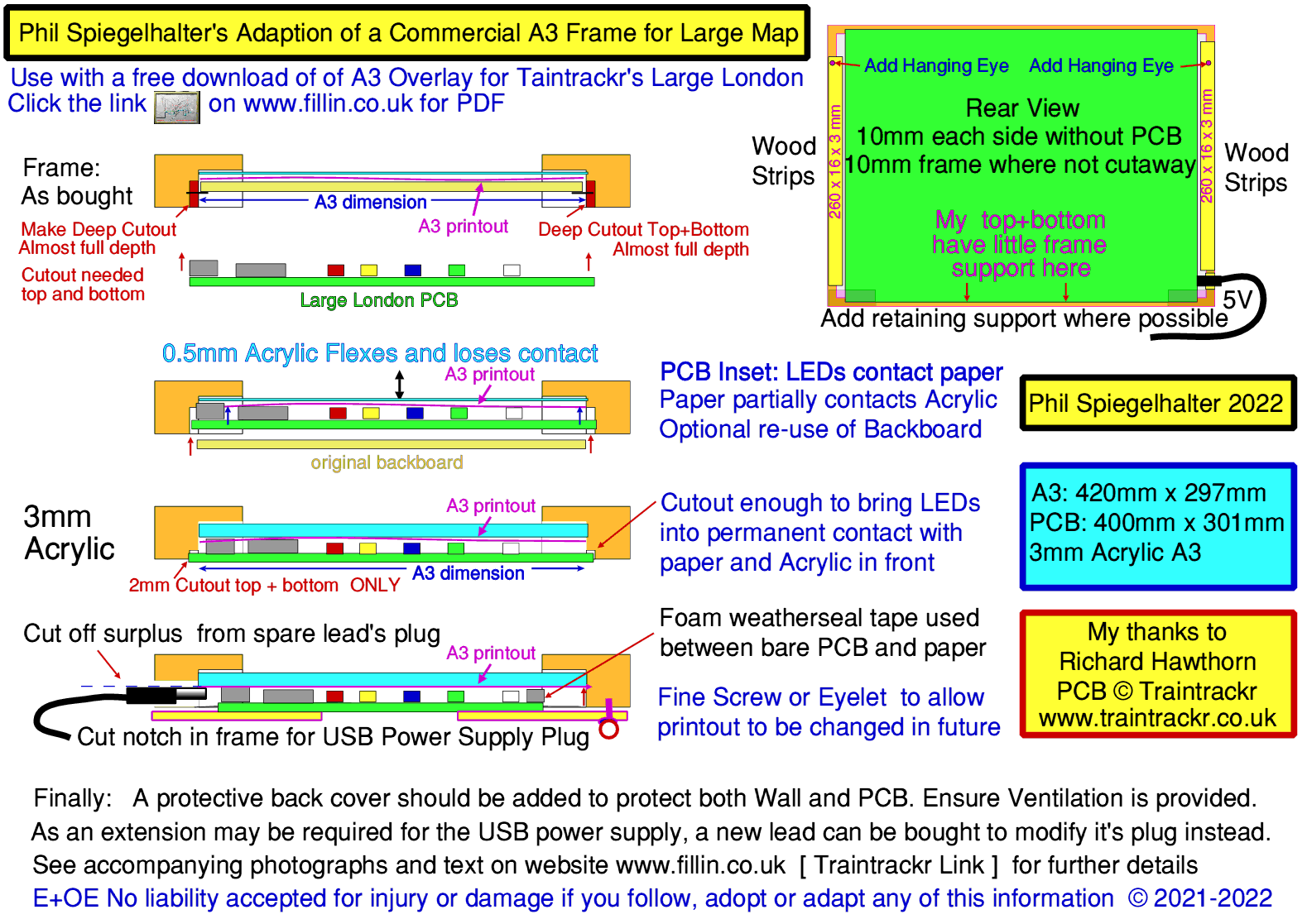
The following is based on my progression starting with a 'commercial' A3 frame bought 'online'.

Frame Adustments

I chose a Hampton Frames OSLOG A3 42 x 30 cm Natural Wood Effect Picture Poster Photo Frame Plexi (Non glass) OSLA3N
The frame-border is 20mm wide by 12mm deep, and the central rebate is a perfect fit for the A3 Printout: 297mm x 420mm.
The frame gives the appearance of being made from compressed sawdust, wrapped in paper, and some care is needed when cutting.

The backboard and glazing were retained by metal clips which can all be discarded...
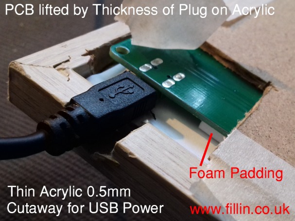
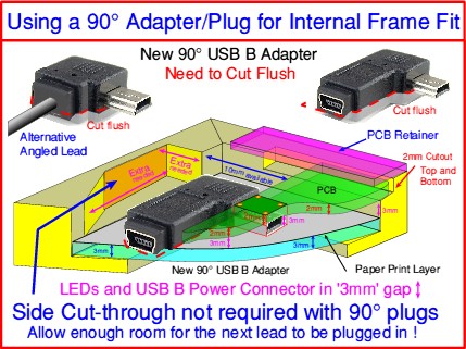
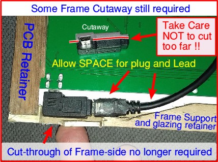
The PCB is about 4mm higher than the A3 297mm, and therefore a 2mm wide rebate has to be cut in the top and bottom frames.

Working initially with the supplied 0.5mm Acrylic Sheet, the 2mm cutouts needed to be quite deep - leaving just 3.5mm of the frame
However, I soon discovered that it flexed too easily; separating from the Paper Print if the frame was angled forward.

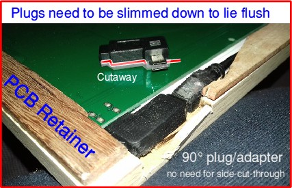
I therefore ordered an A3 sheet of 3mm Acrylic [Acrylic being stiffer than Polycarbonate], which reduced the depth to be cut to about 2mm
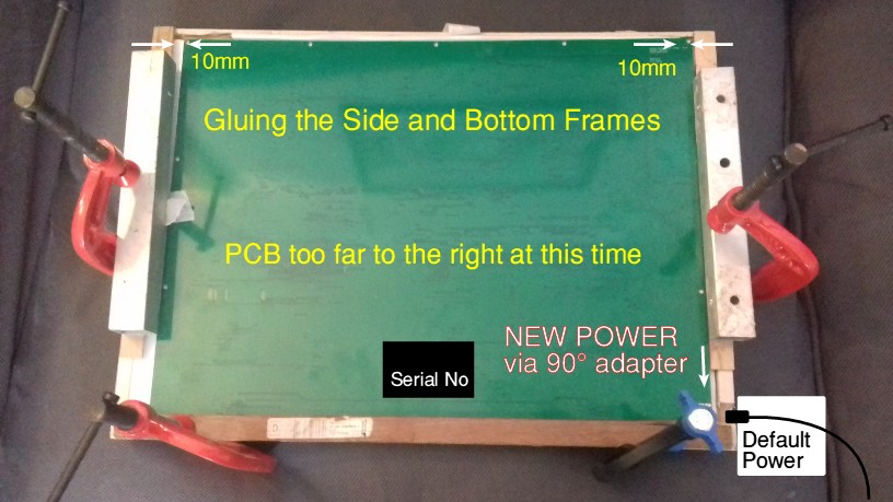
This brought the inset PCB flush with the rear of the frame, so that a wooden strip glued to the bottom piece could act as a retainer.
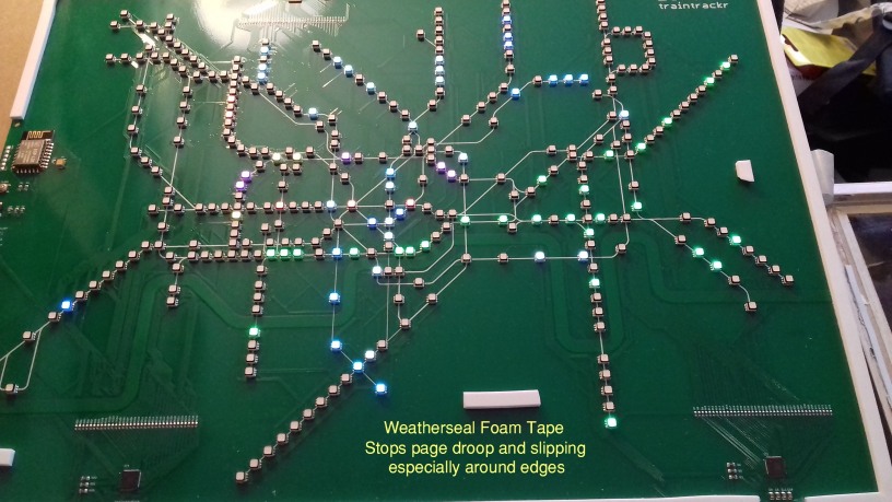
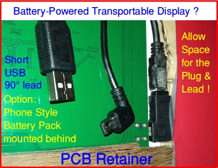
Having previously cut deeper, I used Weathersealing foam tape to pad-out the gap, helping hold the PCB in place laterally too:
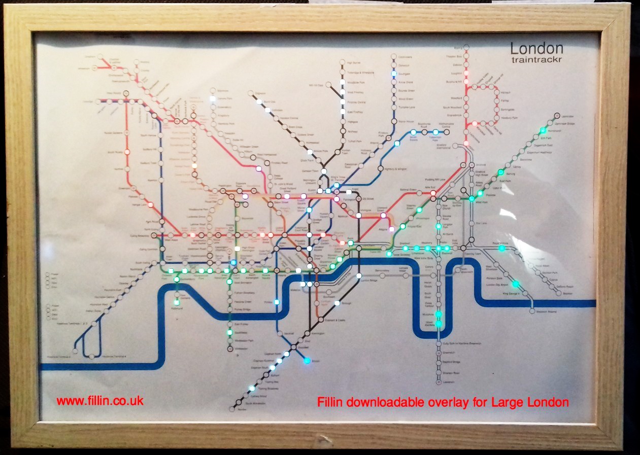
With the glazing and printout in place, the PCB was placed behind, and powered up to check the registration with the stations.
The 3mm weatherseal foam tape was also used around the PCB, and where there were no stations, to push the paper forward.

Horizontal Positioning of the PCB to Register with the Printout

The paper is simply located by the frame and the Weathersealing Foam tape so as to make changing it in the future easy.
The wooden strip across the bottom retains the PCB securely whilst allowing it to be positioned horizontally.

There should be approximately 10mm gaps either side of the PCB which reveal the paper print.
Once all other construction had been completed, strips of Birch were glued to the upright side frames; overlapping inwards to retain the glazing,
and to provide a firm support for hanging eyelets as the original backboard will not be re-used.
Two short removable sections will be added across the top to hold the PCB firmly in place.

newpower.jpg - 92Kb
Power Connections - First Version
Power has to be applied to check and adjust the registration.

My version of the board uses a USB B connector on the component side, and with the Straight Power Plug provided, the PCB will lift in that corner.

pcb_lifted.jpg - 75Kb

Whilst a rough check can be made with the original glazing sheet because the PCB is flexible enough to remain lifted in the corner
to use this 0.5mm sheet with the PCB flat would require all of the frame to be cutaway!

With the straight plug, the side of the frame still needs to be cut away, down to the level of the rear face of the 3mm Acrylic,
Surplus plastic also needs to be carefully removed from the plug, on the side away from the PCB, almost as far as the metal shield.
Otherwise the PCB will not lie flat, and the frame hang straight on the wall. I recommend buying 2 adapters 'just in case'.

Second Version:
Using a 90° left-handed adapter, or 90° left-handed extension lead avoids the need to cut through the frame.

As can be seen from the drawing and photos below, a 90° left-handed adapter can be fitted within the outer boundary of the frame.
This still requires some of the frame to be cut away, down to the level of the back of the 3mm acrylic, or slightly further.

As before, the Adapter must have the surplus plastic cut away to near flush with the metal shield as this is flush to the acrylic.
The Straight-plug lead now plugged into the Adapter is effectively captive - requiring the PCB to be removed to unplug/plug.

By using a short adapter lead with 90° plug, a rechargable 5V Battery Pack could be mounted on the rear of the frame for 'wireless' power,
or to connect to a more easily removed power lead.
90a.jpg - 68Kb 90d.jpg - 57Kb
90c.jpg - 69Kb 90b.jpg - 54Kb
Phil Spiegelhalter

Click here to return to the Fillin Home Page


Edited in HTMLEdit Studio on 11-18th January and updated 10th August 2023 (c) Phil/Lin Spiegelhalter 2022-24
PDF v9-11 by Paul Griffiths