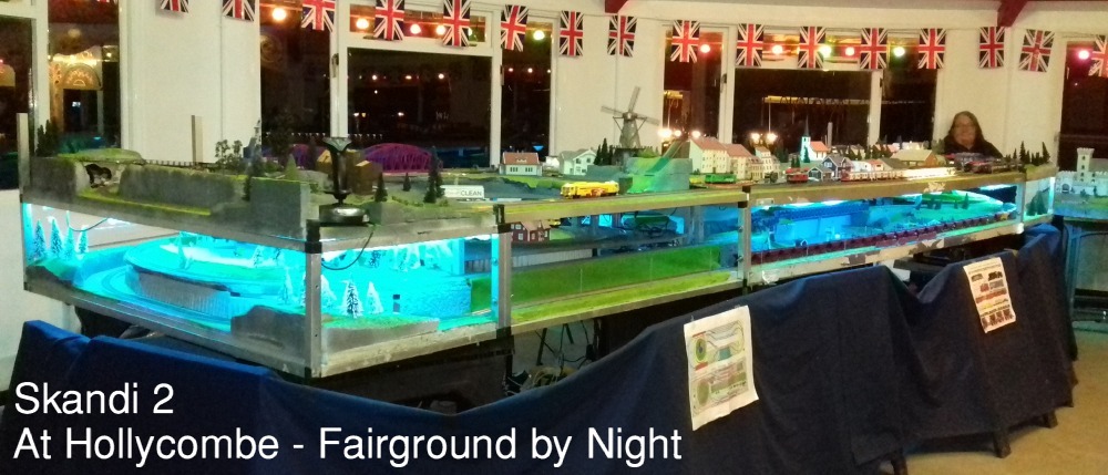
 The replacement Skandi2 AFTER increasing the separation between levels and therefore building a new helix linking them Seen here in an October Evening at Hollycombe with the Fairground operating just outside the windows. 5 connected loops on 3 levels + shuttles. 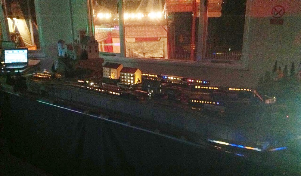 The original dual-level 'Skandi Demo' was built to attract visitors to a Society Stand which previously only had a static dsiplay of models and books. (The layout also gave us somewhere to run our collection of Scandinavian Rolling Stock - with 4 hidden tracks on the lower level for variety. Also seen here at a Hollycombe Fairground by Night - Click Picture-Link for Skandi Demo 1a and 1b 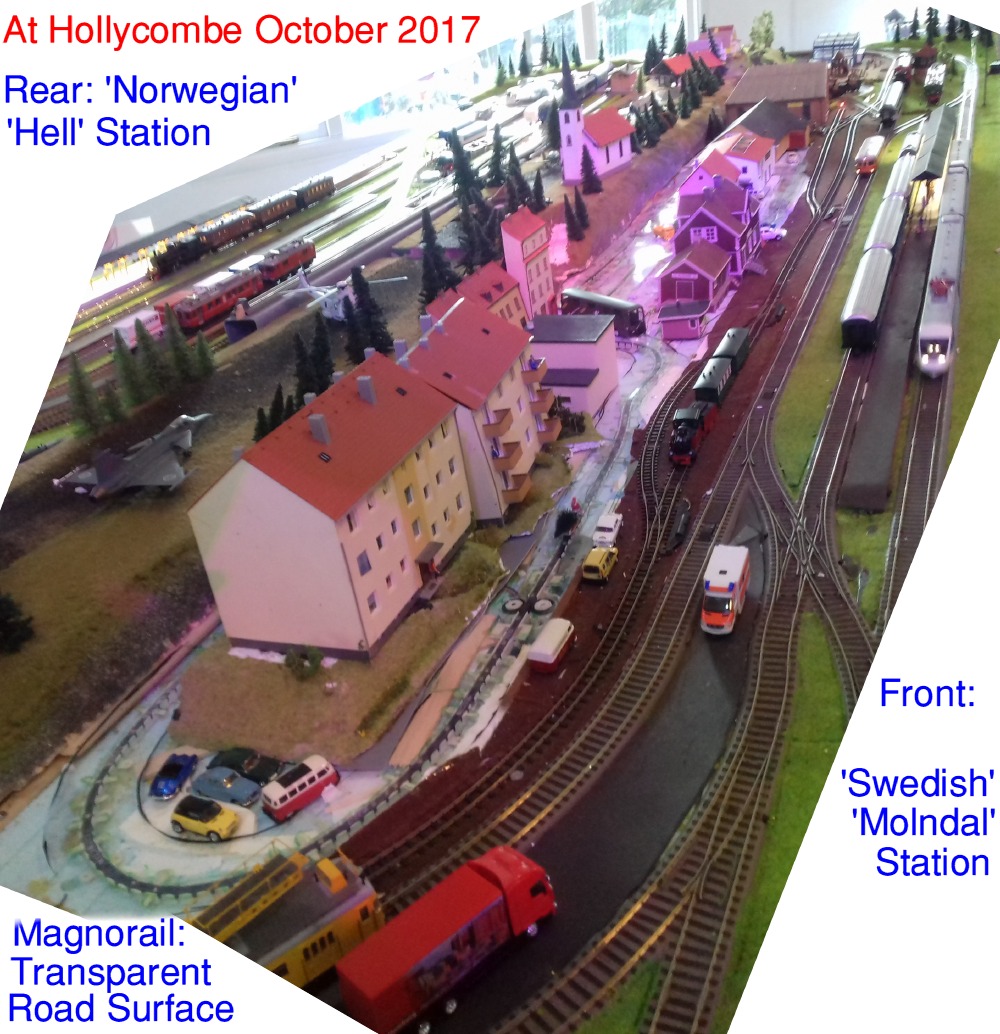 The original Magnorail® Roadway for Cyclists and Cars - revealed here with a transparent road surface. This was later rebuilt as 2 separate loops using the Mk2 version, and given a grey plastic card road surface. Moving Skiers and boats will be added by the same method. R/C vehicles CAN be freely driven too - but with some restrictions! 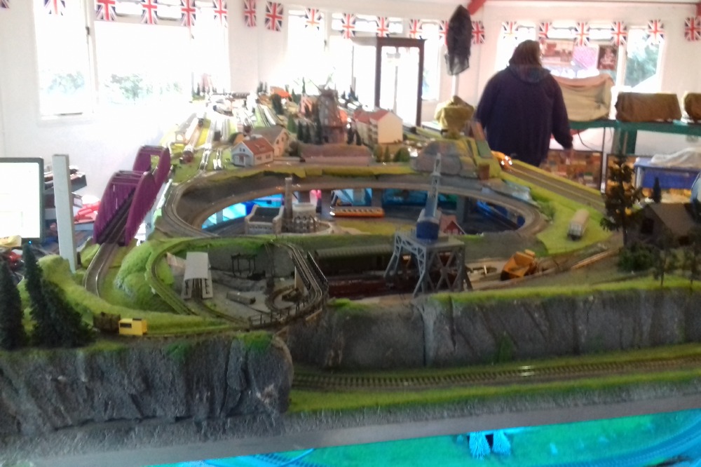 A view across the 5.4m length from the H0f logging railway end. The Roco Logging Crane is operated by visitors to load wagons using the Joystick. 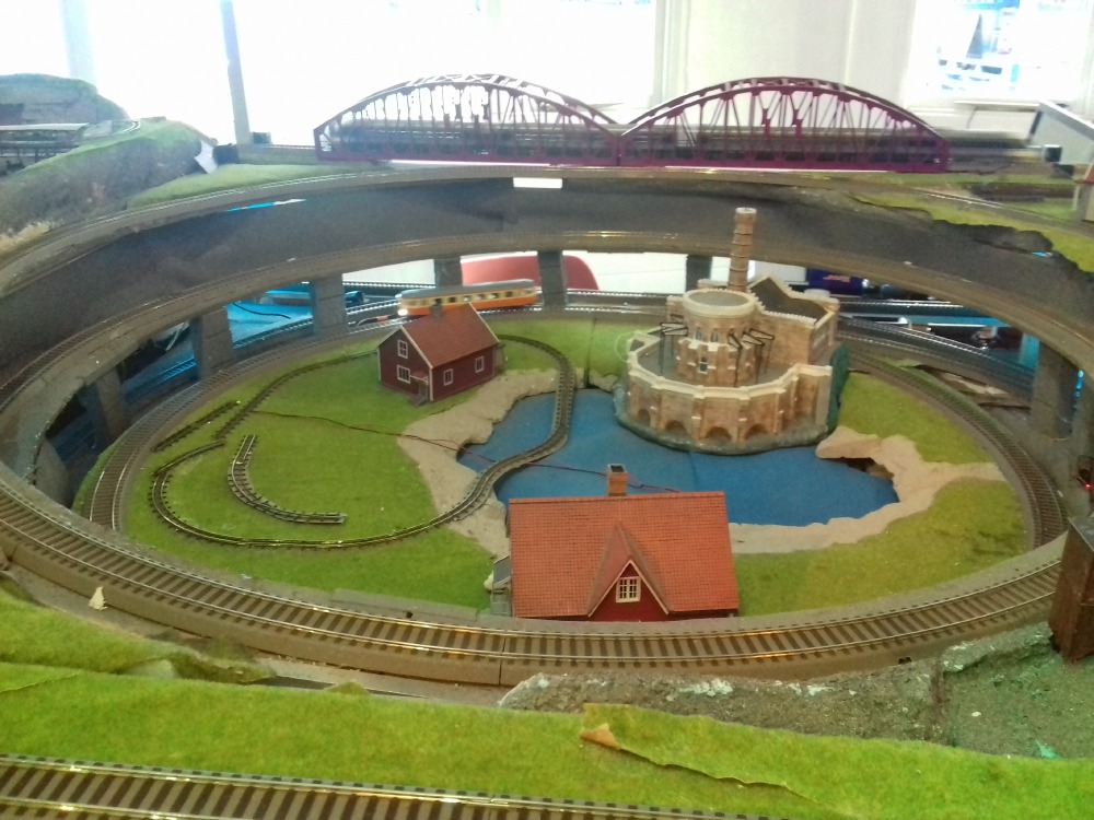 The New Helix Frame is 1.2m x 1.1m - and now modelled as a sink-hole with campsite: the front and rear passing-tracks are separate pieces. The standard gauge loop is normally run on a separate dcc system, and operated by visitors. It can also program locos without interrupting the main layout. 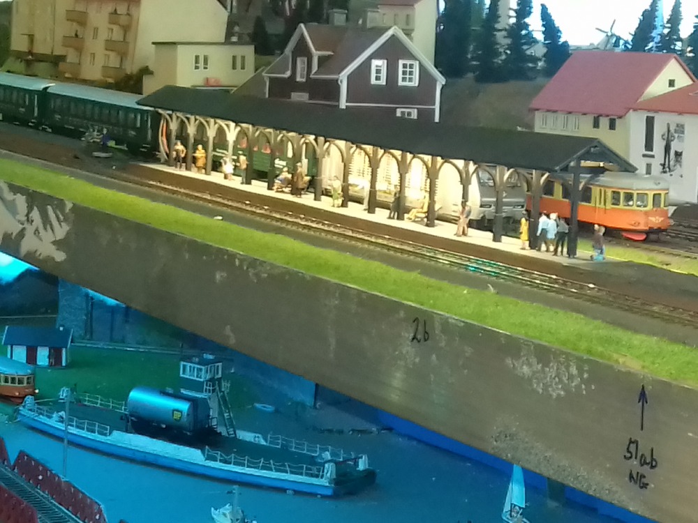 Lighting of Platforms was built in from the start because of the expected night time use at Hollycombe. Most coaches are also lit by LEDs. An interest in Sleeping Cars ensures that a set is run during the evening sessions of Fairground by Night. 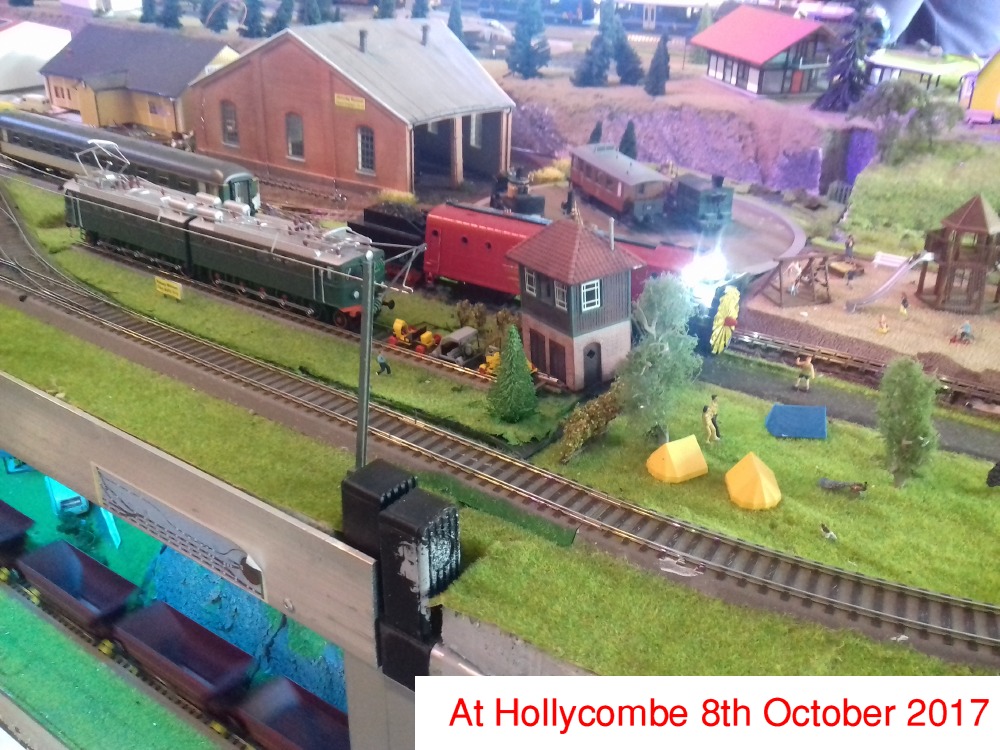 Following the example of several Swedish Stations; 'Molndal' has a growing 'Museum' area by the old loco shed - Stock is changed regularly An Iron Ore Train and a small train ferry can be seen on the lower level. Trains can run to and from either upper level station via the Helix. |
|
This layout was built to replace the smaller, 3m Skandi Demo1 which was created to attract interest to a Society Stand Construction is 25mm x 25mm Aluminium Square Tube frames with XPS foam sheets. Roco Geoline track was used ( + now some Rocoline ) Pre-covid, most of its appearances were at Hollycombe - Steam in the Country - Liphook, but it also ventured to Ilfracombe IMRS Show 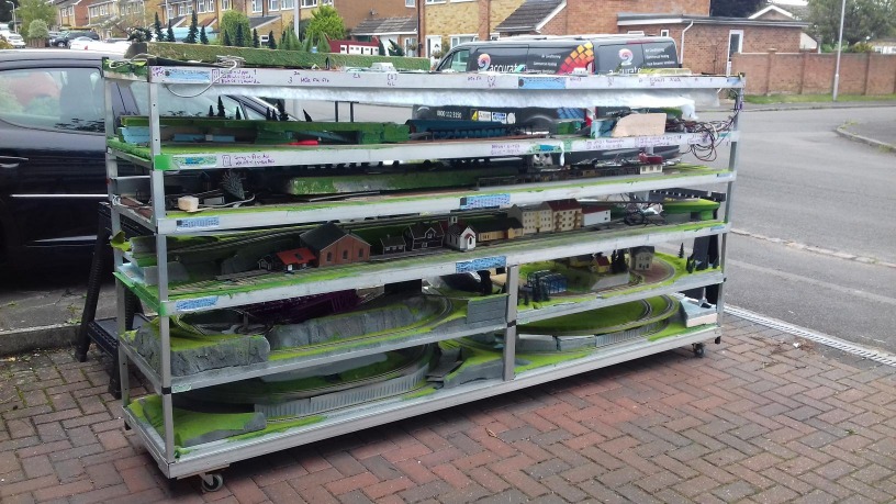 The 3 metre long 'Tea-Trolley' of Skandi2: The layout without stock is light enough to be carried by just 2 people. 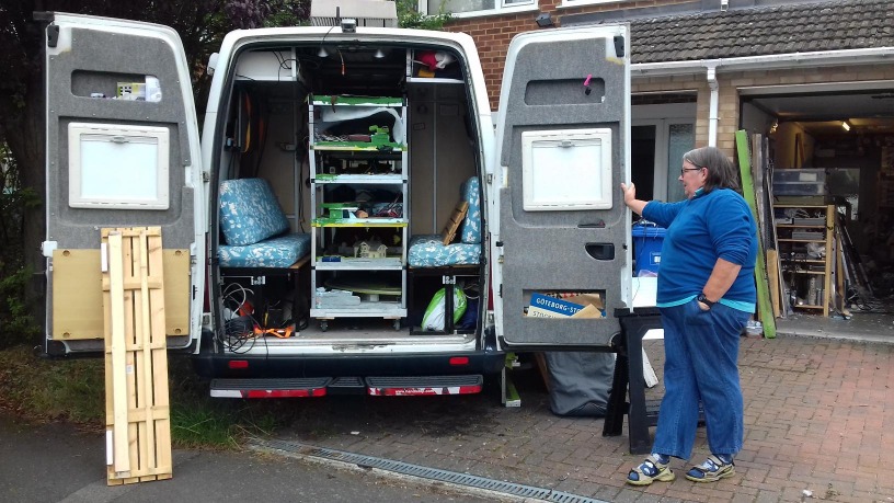 Skandi2 T-Trolley fits down the centre of our Camper Van - The Helix then fits on the right hand side, stock on the left. 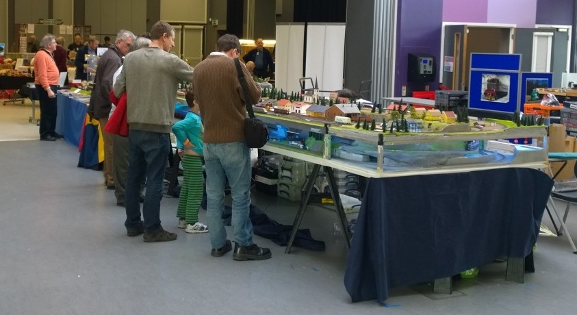 The 1st Outing of Skandi2 was to Eurotrack in Southampton in 2016 - The Helix section was not inserted this time. The separation of levels was increased by 50mm after this show, and the Helix section rebuilt for the extra climb 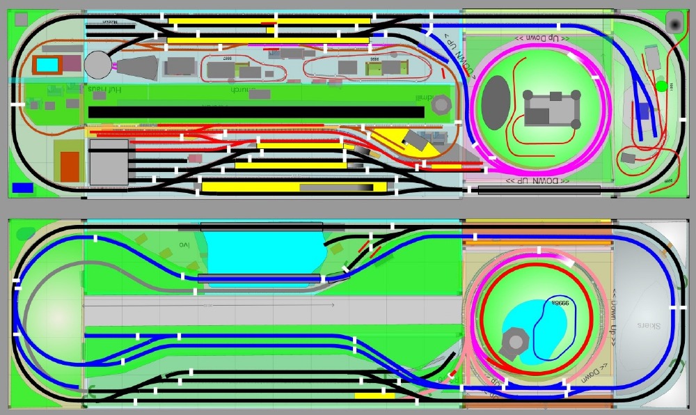 The Upper and Lower Level track plans of Skandi 2: |
|
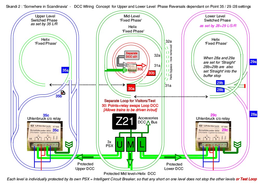
The mid-level is common to the Helix, and 'fixed phase': Upper and Lower levels are then phase-switched simultaneously with their respective entry/exit points. There is thefore no limit on the train length - a 3.5m Iron Ore train can be concealed on the inner loop. The schematic diagram indicates the dcc addresses of the Magnorail bicycles, H0f railway, Timber Felling and other Effects - ALL DCC controlled GREY is the Inner Loop which can store a long Iron Ore Train. Blue is the Mid-level and purple the Helix. Black is either Upper or Lower Loop The RED loop inside the Helix is either a separate DCC system for visitor/programming use OR the main dcc when the points are set for access [The idea being that a multiple unit can be driven into/off the loop for programming, and the loop can run independantly in case of main DCC failure] Track-Section Modules are available for inclusion to add Track-Occupation to Large Screen and Tablet Displays - Limits shown by White Breaks [Move to Home Page;Intro] The Simplicity of DCC Wiring a Layout - Total Control from anywhere around the layout without tripping over wires. We have often operated our portable layouts when standing behind the visitors watching the layout. We also encourage visitors to operate parts of the layout: The Multimaus handsets are intuitive and easy to hold, Joystick control of a crane allows them to load and unload wagons. The Shunting puzzle offers everything from a beginners first control of a loco up to 'the full shunt' of 5 wagons from 8 into a specified order ... without manual intervention 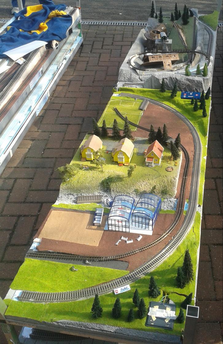 The 1.5metre long ends are stacked end-to-end on the lower level of the T Trolley, and the 3metre sides stacked above 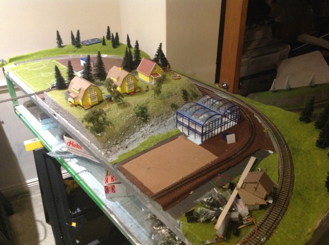 These Layout Photos taken during early construction - mainly for remote discussion via email with my brother |
As built: Roco MultiCentralePro for the main layout and an old Roco Amplifier 10874 for the Test/Tourist Loop updating to: Roco Z21 (black) for Main layout, and probably a z21 (white) for the test loop to make that wireless Z21 series allows accessory dressing to be shifted by 4 to the 'new unified standard' - making use of DCC Concepts ground signals and micromimic indicators practical: Also awaiting fitting are Digikeijs Occupation Sensing modules - which require electrical isolation of sections - something I prefer to avoid ! ( by using Optical and RFid sensors ) MultiCentrale Pro links with 'Rocomotion' software to provide an on-PC-screen display of track and train control - with feedback detection .... and Z21 transfers that concept to Android and iOS devices. Existing Multimaus Pro Handsets may continue to be used by connecting the MultiCentralePro into the Z21 Track used on this layout is (with a small exception) Roco's Code83 GEOline ready-ballasted sectional track. This is historically because it replaced Skandi Demo which 'used up' set track supplied in Roco and a Trix Starter Sets at the time. My preferred track is Rocoline's Rocoline with 'rubber' ballast - also Code83 but more durable and quieter running than the brittle GEOline but all my available stock was allocated to our 00 loft layout ... but Roco have now reintroduced permanently the Rocoline track. Any future rebuild of parts of Skandi2 might therefore use Rocoline track - with its greater geometry options. As a transportable modular layout, the interconnections between boards need to be simple, effective and reliable. 6.3mm spade terminals in car-style plug and sockets: DCC busses are Accessory Bus, Upper Level track, Mid-level track and Helix, Lower Level track, with 12Vdc and (historically) 16Vac for local power distribution. 12V RGB LED multi-colour lighting strips mounted on the frame provide controllable lighting of the lower levels using a separate 12V supply. TRACK dcc is distributed via PSX intelligent circuit breakers for each level. Simple push-button-reset breakers are used for AccessoryDCC and 12V/16V. Apart from the obvious safety-factor of including circuit breakers - it is also designed to aid diagnosis by separation and keep other levels running. Increasing levels of LED layout-lighting ring will need it to be split into 2 sections each with a 5-6 Amp supply - also making fault tracing easier. Move or duplicate this section to Beechingless Barnstaple ? FAULT_FINDING with INBUILT Design and Assistance [Why some may claim their layouts run 'faultlessly'; I do not, have spent much of my life installing and teaching maintenance / faultfinding on electronic equipment - I used to cite my Zero-1 layout as an example of the disadvantages of an unprotected 'single circuit' for all, and is another reason I prefer totally separate Optical and rfid detection for train tracking and occupancy than current detection via isolated sectors. Skandi 2 Somewhere in Scandinavia has 3 separate and individually protected dcc track distributions - so in case of a fault only 1 level should come to a stop. The Tourist/Test loop can remain running, and also the moving vehicles (Magnorail) and Logging Crane - while the 'main layout' level is diagnosed. Two Examples: The Zero-1 layout - sudden dead short across all track + accessories - thankfully only 1 train had been moving at the time: but it was in a tunnel section, and I eventually had to lift the points at either end to isolate tha length of track ... it ws a single strand of metal wire laying in the ballast that was disturrbed bt the passing train that caused the short circuit that stopped everything] 2nd: Current loft layout Beechingless Barnstaple Separated 'power districts' and inline DCC Voltage and Current meters- a short occured with 1 train moving while I had a visitor. The sectionalisation immediately identified which 'power district' - and each of these has 'WAGO-style' lever-released connectors allowing SUB-scections to be isoated easily - without needing a screwdriver. This reduced the area-of-the-problem to a small geographic area (ny sub-sections largely follow 'boards' and then 'through routes' or the 'freight yard'). In built diagnostics are Buffer Stop Lights, Station / Street lights, and even built-in LCD Oscilloscope (for dcc demonstrations) and Track Voltmeters. On this occasion, checks in the area of the derailed loco did not find the cause of the problem - and then I realised that I had had a 9V Metal-clad battery in my hand at the time of the derailment - and put it down onto the track next to me so as to re-rail the loco .... thus causing 'the fault' to continue in a new 'unrelated' loction !! Tracing was with a meter measuring (unpowered track) resistance and moving on the direction of least resistance .... where I then found the battery on the track - lifting it clearing the fault. The most common cause for stoppages on a (dcc) layout using live-frog points, is over-running across a wrongly set V. With a PSX protecting the track, flashing and LED as it tries to reset the power, controlling the points via the Accessory Bus fed directly from the controller ( via std resetable cutout ) allows any controller to correct the erroneous point - and train(s) resume moments later. |
| Or Click for: G Scale Garden Layout or G Scale Portable Layouts (mostly seen at Hollycombe) |